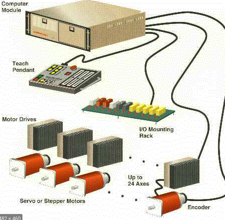
Industrial automation today is spearheaded by dexterous manipulators and warehouse mobile robots. Manipulator arms dominate the manufacturing and post-processing industry, whereas mobile robots are the new-generation inventory management machines. Manipulators have been on functional on assembly lines, packaging stations, palletizing tasks and sorting tasks since the last quarter of the 20th century.
Until a decade ago, manipulators used to be bulky and lacked any perception capabilities. They were and still are, largely deployed for position-controlled repetitive operations like automobile assembly, welding operations and pick-and-place tasks. Such conventional tasks only require moderately-acceptable levels of smoothness and accuracy in motion and reliable performance.
However, with the advent of collaborative robots and expansion of the horizon of robot applicability in industry, feature requirements have also exploded. The 21st-century industries have adopted robotic automation instead of manual labor for tasks that could utilize robotic performance and consistency and help get rid of human labor involvement at monotonous tasks. These tasks include pressure welding, metal polishing, deburring and other force/torque based applications with/without human presence around.
Eventually, sophisticated operational features and performance benchmarks have engendered the need to use more complex and inclusive control techniques on manipulators, both at the actuator as well as robot level.
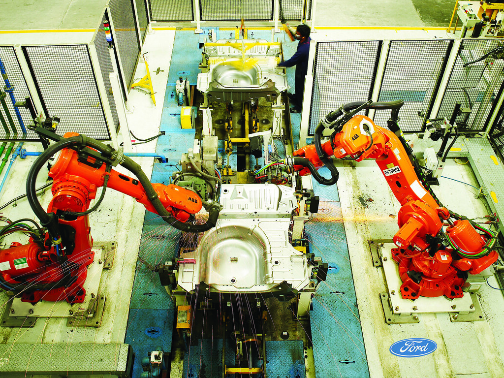 Manipulator Arms on an assembly line
Introduction
The control algorithm is the most important component of the system to ensure that the robot performs the user-desired actions. Traditionally, manipulators have been using electric rotary actuators and hydraulic and pneumatic actuators on revolute joints as well as prismatic joints. Such actuators have been operational largely in position control mode in a closed-loop system.
Control mechanisms for robots can be categorized into two broad categories - the high-level/robot-level control and the low-level/actuator-level control. Both levels of control are extremely important to realize the desired behavior of the robot.
While the low-level control ensures that the actuators function well independently, they are susceptible to external factors like loading on actuators, dynamic-effects of the kinematic-chain and the forces arising from them. This necessitates the usage of more complicated control techniques at the robot level and account for the dynamics of the system. Majority of these robot-level control techniques use a model of the robot representing the mass and its distribution, relationship between joints and tip forces and the effect of gravity on the robot, among others.
In essence, the robot-level control techniques govern the definition of the reference signals for the low-level actuator control loops considering the system interaction and behavior over each iteration.
Actuator-Level Control
Industrial manipulators have largely been revolute joints powered by electric rotary actuators, aka servos. These servos comprise of a motor, a transmission unit and a feedback element. Position and torque values are the feedback measurements used when controlling the servo in position or torque mode, respectively. Essentially, closed-loop control is the basic template for any control-system to abide by desired physical values.
The performance of position-controlled systems depends on the resolution, accuracy and speed of the position information provided by the encoder while feedback for the torque-controlled systems, it depends on the motor current feedback or mechanical torque-sensors.
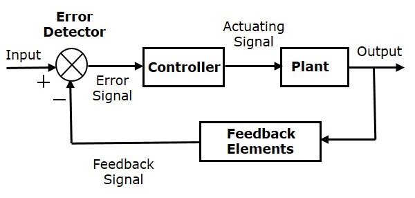 Closed-loop Control System
PID CONTROL
Proportional-integral-derivate control is the most traditional control technique that has been effective toward efficient servo control. PID control basically modifies the control input signal depending upon how strongly does it drive the controlled output parameter (position/torque/velocity) of the actuator to desired values. The PID controller is ideally meant for set-point tracking but fairly useful during continuous motion in robots as well. For servos used in manipulators, the setpoint(controlled parameter) could be position or velocity or torque but is generally a position-controlled loop.
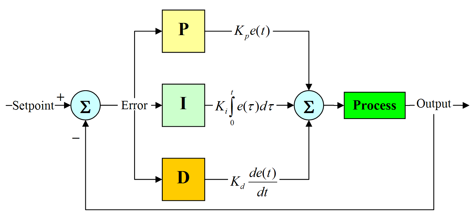 A continuous-time PID control loop
-
The P(proportional) component is responsible for magnifying the error(difference between desired and actual values) in tracking and can cause oscillations about the desired value in case of error changing directions.
-
The I(integral) component is responsible for accumulating the error over time and modify the input signal to overcome the same. While it is useful to improve steady-state performance, it can be a source of induced oscillations in real-time dynamic systems like servos.
-
The D(derivative) component is responsible for estimating the rate of change of error and manipulate the volatility in the input signal that is needed to reduce the error. The D term is essentially a damping component and subdues the impulsive nature of the P component. It improves stability and reduces settling time as well as the aggressive nature of the controller.
I created a PID-control based servo simulator some time back. - You could check it out here!
 Internal velocity loop allows controls the impulsive behavior of the change in position
GAIN SCHEDULING PID CONTROL
In theory, gain scheduling for non-linear systems is manipulation of the control hyperparameters depending upon the variations in several observable parameters. Observable parameters of a system are those dynamic values that suggest the change in operational regions of the non-linear system and generally define the linearizable zones of the same.
Often linearization of non-linear systems derives parameters that do not suffice for linearity over the complete operational range of the system. Thus, the control parameters do not have acceptable performance outside those regions.
Specifically, in terms of PID control, observable parameters could be the rotational velocity. This is because the plant model changes with these physical values and to respond accordingly, the PID tuning parameters are also required to be modified on the go.
Intuitively, it can be understood that a rise in temperature reduces the viscous friction and other resistive forces in the motor and thereby reducing the torque needed for a comparable motion at a lower temperature. Thus, the P component of the PID control could be reduced to avoid oscillations.
Similarly, increasing velocity increases the nature of impulsive response and reducing the control values could better the dynamic performance of the actuator.
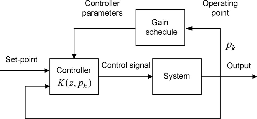 Gain Scheduling based on different observable parameters
FEED-FORWARD CONTROL
Feedforward control is a term generally used for systems where the control signal is transmitted from the plant with a known response, while the system is attached to an unmodelled load component that eventually manipulates the desired behavior. With reference to a motor/actuator, feed-forward control is when the motor is expected to respond to the input in a predictable way but because a load is connected to the motor, it can cause unexpected behavioral changes.
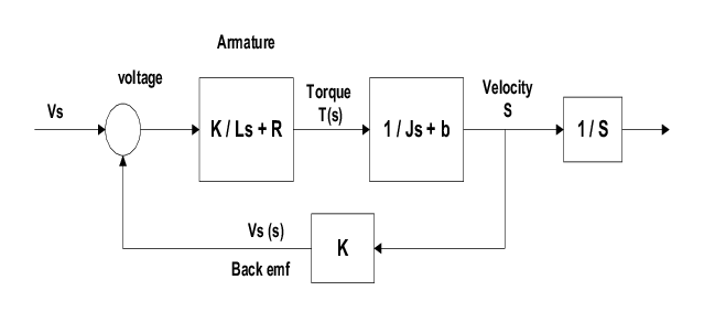
A DC motor system model
Classical motor control theory defines a transfer function that relates the input values to the output. The transfer function for a DC motor is given as the relationship between the input voltage and the output rotational speed. Integral of the rotational speed gives the position of the rotor shaft. This is a very rudimentary example of a DC motor transfer function and exploring the different DC motors and their different transfer functions is beyond the scope of the article.
Feedforward control determines this value of control voltage signal to obtain desired position/velocity of the actuator shaft.
Actuator control is a single-input single-output system and coupling effects or other external effects could be modeled as disturbances to the individual systems. Individual systems involving such complexity are beyond the scope of this article and in general are handled at the robot level.
There are several other advanced algorithms for robot control, some also applicable for actuator level control like the model predictive control and the sliding mode controller which is beyond the scope of this article and is discussed as a separate article here.
Robot Level Control
A robot manipulator is a multi-input multi-output(MIMO) system. It is a complex system where kinematics and dynamics of the system are all related along the complete chain. The interactions between the individual actuators and the robot with the environment may/may not result in plenty of unprecedented behavior.
Thus, for the robot to be a high-fidelity and high-performance system, the complete physical system is modeled and so is the interaction with the environment. Often, control algorithms are designed to be adaptive to the uncertainties in the model and be functional over an anticipated range of variations or maybe even beyond them.
Euler-Lagrangian approach derives the dynamic model of the robot that relates the actuator position, velocity and acceleration to the various torques at all joints of the kinematic chain. Actuator dynamic parameters induce several centrifugal and centripetal forces, mass and load propagation and reactive forces on the different joints and computed torque control accounts for all of these using the mass matrix, coriolis matrix and the gravity matrix.
This equation lays the foundation for all model-based control techniques for robot manipulators and with certain modifications is enhanced to support several performance and operational requirements.
 Where M = Mass matrix; C = Coriolis effect matrix; G = Gravity matrix
The broad categories of robot control are feedback control + feedforward compensation, robust control, adaptive control and intelligent/learning based control.
COMPUTED TORQUE CONTROL/INVERSE DYNAMICS
The robot equation above relates the robot joints’ position, velocity and acceleration to the torque required on the actuator powering those joints. Computed torque control is also called inverse dynamic control where the desired joint variables are used to compute the joint torques.
The trajectory for a manipulator is defined by the desired joint position and velocity. Designing a non-linear feedback control law u = f(q, q_dot, t) sets up a closed-loop system for the manipulator.
The exact control input used is given as:

Comparing this input control law with the dynamic equation of the robot results in aq = q_ddot. Now, the new control variable aq is designed using the feedback linearization. This introduces the understanding of error dynamics where the error is given as

Using the new control variable aq given below, we find a solution to the problem.

We finally obtain the control law that is a combination of feedforward compensation(providing joint torque for the desired joint acceleration and the current joint positions and velocities) and feedback control that provides torque for trajectory tracking error for the positions and velocities. Eventually,

This control technique needs the exact model to be efficient enough to be used. So, it is generally only used in pure simulation or in conjunction with other high level controllers. A similar setup of this control technique is extensible from joint space to task space using relationships between the cartesian coordinates and the joint angles and analytic Jacobians.
PD + GRAVITY COMPENSATION
Gravity Compensation is essentially not a control technique rather as the name mentions, a compensation measure. It is used to compute the torque acting on each joint of the manipulator due to gravity. These torques are only dependent on the robot configuration, i.e., joint angles. However, the control signal that compensates for this and adds extra torque component contributing towards the error using a PD controller.
The input torque is defined below and ensures a very acceptable limit of tracking and rest errors are handled at the actuator level.

ROBUST & ADAPTIVE CONTROL
The above mentioned control techniques need full system parameter identification and external loads or disturbances, parametric uncertainties and unmodeled dynamics make the above mentioned robot-level control techniques futile. Both of these control techniques ensure reducing tracking error and maintaining stability.
Both these controllers are similar in intent but limited in the scope of applicability. Robust control handles uncertainties within a known range and ensures performance is maintained over the band of allowed tolerance while adaptive control handles the unbounded uncertainties and performs online parameter estimation. Adaptive controllers are limited in scope where ones used for parametric estimation may not be extensible to external disturbances or load.
The mathematics behind robust and adaptive control are very involving. They do use the robot manipulator dynamic equation and try to define/represent the error in system identification. Generally, the new unmodeled component is a function of the joint variables and time.
IMPEDANCE CONTROL
All control techniques mentioned above are defined initially in joint space and only later modified to be applicable in cartesian space. However, in certain tasks; it is important sometimes to handle robot behavior as a whole, essentially in the task/cartesian space. A simple example would be robot self-collision detection which is essentially a robot level act and is basically defined by joint angles.
Impedance control presses a dynamic behavior between the end-effector and the external world the robot is interacting with. It specifies a dynamic impedance, via a spring-mass damper system. Usually, the impedance is linear and decoupled in all individual cartesian directions. Impedance control is applicable for robot tasks like deburring, painting, welding and other small-force little-intrusive contact tasks.
Impedance control assigns forces in the individual cartesian directions controlled indirectly by position. Thus, the definition of forces along the directions is a trade-off between the accuracy in position against the contact force along the same.
It uses the task space definition of the robot manipulator dynamic equation to define the control system. The Jacobian, joint-torque and end-effector force relation and end-effector force defined as a spring-mass damper is the basis of this control system.
As a general rule, large impact forces are avoided with the environment by using large inertial/mass constant B and small spring constant K in direction with anticipated interaction. Directions that would most probably not have any contact/external interaction shall have large K and small B. Spring damping constant D is only used for transient states. Intuitively, in the direction of no contact, the motion is stiffly controlled while in those with contact estimated, the motion is softly controlled.
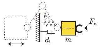
Hybrid impedance/force control is an extension of the normal impedance control setup that allows for simultaneous control of position and force. There are a few more sophisticated robot methodologies for control of unmodeled robots, like use of reinforcement learning to train and abide by a trajectory for various tasks.
The further remaining/unexplained control techniques like robust and adaptive control among others would be explained later
