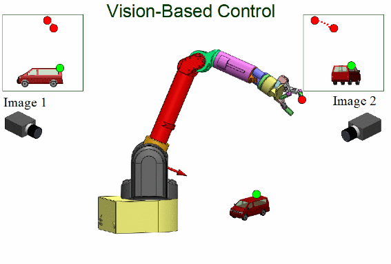
Visual Servoing is one of the most used robotics in the industry for automation. It involves using computer-vision based realtime feedback of the task space for online control of manipulator end-effector pose while performing tasks. Servoing refers to using a closed-loop feedback mechanism to manipulate reference input signal to a system while eventually driving the system to the desired target. Extracted features from visual information relate the robot current configuration to the task at hand and the system generates high-level pose control commands towards task completion.
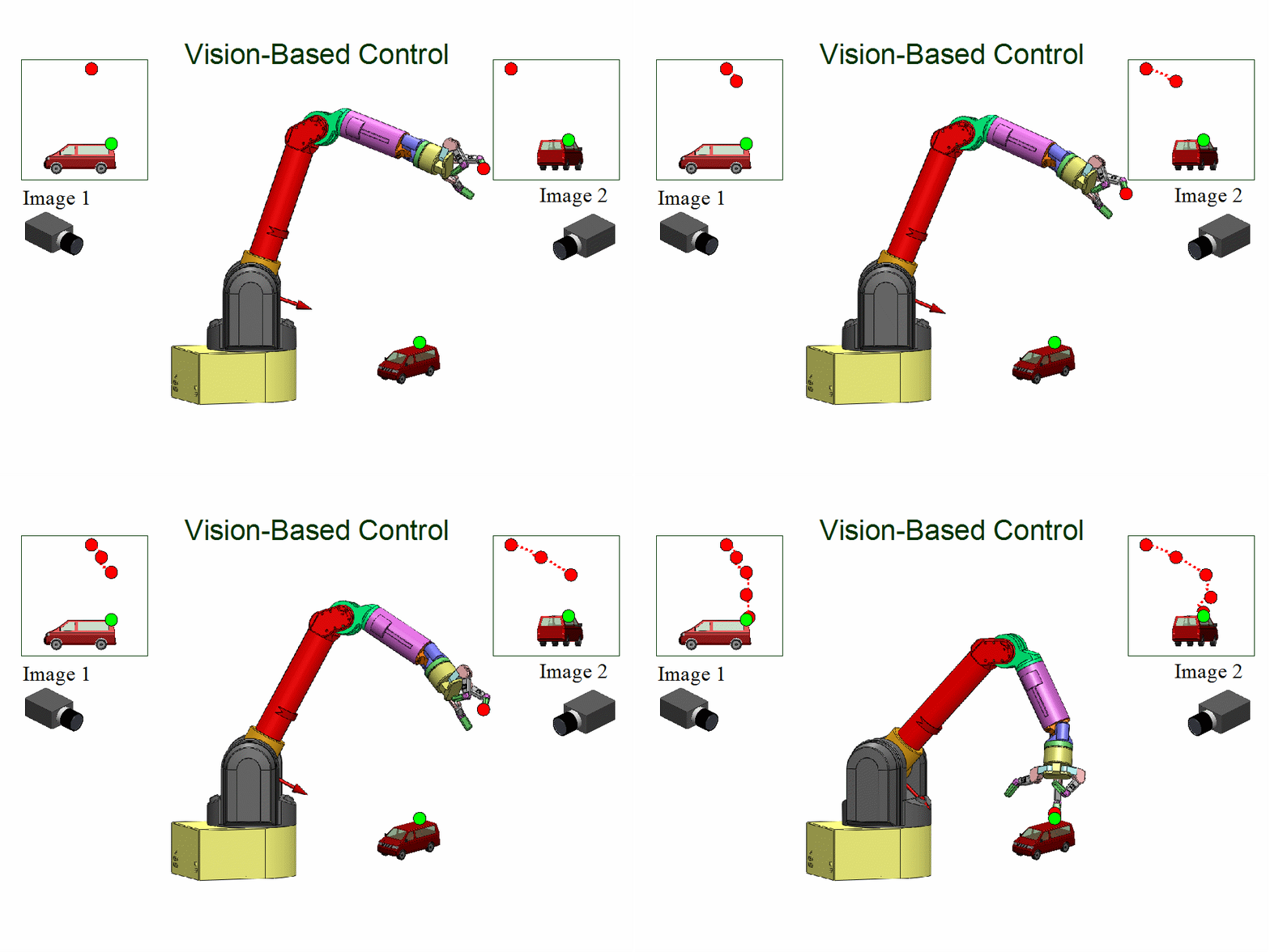 Visual Servoing
Introduction
Image processing represents the physical state of the object in the world such that it can be related to the robot pose. The fundamental geometric relationship between an object in 3D space and its projection in an image helps connect the visual feed to the world and the robot. Visual servoing is dependent on robot pose estimation, robot control and realtime image processing. The kinematics and dynamics of robots vary depending on the model thereby changing the control instructions.
Image processing is used for extraction of several features like points, edges and gradients in images. Such features help in segmentation, object detection and recognition. Such image features are macro level properties that are obtained after batch operations on individual image pixels. The higher the pixel resolution of the image, the better are algorithms at processing the image and obtaining accurate features at the expense of increased computational expense.
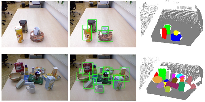 Object Detection, Object Recognition and Segmentation
Visual servoing is a realtime operation and thus involves interpretation of features in one still image or multiple consecutive images or streo images or image flows.
Visual servoing for robot manipulators has two main paradigms based on camera mounting positions; eye-in-hand and eye-to-hand. Eye-in-hand paradigm has the camera mounted on the end-effector of the robot and moves around with it and thus, everything that the robot sees in the world is with reference to the end-effector cartesian pose. The eye-to-hand paradigm has the camera fixed in the world and all observations from the camera are transformed to robot frame.
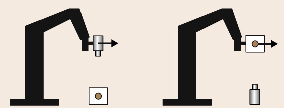
Eye-in-hand and Eye-to-hand paradigms
Another feedback-interpretation based category of visual servoing has two direct and indirect servoing types that generate cartesian poses for the robot and joint angles for online motion respectively. The direct method is easy to use but slow while the latter is complex and fast.
Visual Servoing Schemes
There are two most important visual servoing schemes - position-based visual servoing(PBVS) and image-based visual servoing(IBVS). PBVS uses the visual features to reconstruct the 3D pose of objects of interest and compare it with the current pose to generate a cartesian error that the robot needs to operate on and converge onto the goal. IBVS scheme uses the 2D image of the world, obtains values of the relevant features on them and then manipulates the robot around until the values for the features converge to the desired ones.
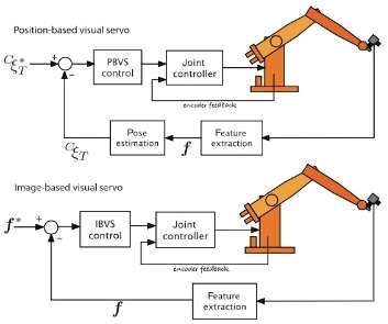
PBVS and IBVS
POSITION-BASED VISUAL SERVOING
The two main components of PBVS high-level operation are computer vision and robot kinematics. Computer vision is responsible for intepretation of the scene, extraction of features and representation of the same in 3D space. Thereafter, the attempt to diminish the cartesian error is translated into robot control instructions.
3D scene reconstruction from visual information makes it important to have accurate camera calibration and pose information such that knowledge about the world is correct and directs the robot to the right location in space. It is important to have accurate geometric transformations between the camera and the world and the camera and the robot end-effector.
 Position Based Visual Servoing
In the PBVS architecture, feature extraction from images is an easy step but 3D pose estimation from the visual feed is sophisticated and is very susceptible to many factors. This desired pose is generally derived based on the pose of the object to be operated on, by the robot. For instance, a pick-and-place task with static start and end poses defines the robot end-effector pose for the grasp/pick action as the desired pose and visually servos the robot to the same.
The reference control signal for the robot is the desired pose ( pdesired = (xdes, ydes, zdes, αdes, βdes, γdes)), comprising of the position and the orientation of the end effector. Almost always, the robot current pose is obtained solely via the kinematics model and the vision system obtains the object pose as an independent exercise thereby making the calibration phase very critical.
IMAGE-BASED VISUAL SERVOING
IBVS paradigm of visual servoing generates errors between desired and actual state/values of features in 2D images. Thereafter, the error is translated into robot relevant control commands and the robot is maneuvered until those values converge.
Given that IBVS does error computation and online feedback within the image plane itself, it is immune to the calibration parameters and inaccuracies. Contender image features that are to be converged to, could be as simple as positioning of the object of interest in the center of the image canvas or aligning the edges in image to the one from a standard image.
 Image Based Visual Servoing
Steps involves in IBVS have several sophistications and challenges. The repercussions involve delayed processing, computational limitations and image resolution.
- Frame rates, noisy information, ambient-lighting inconsistencies and latency are the most challenging aspects of image acquisition and online processing step.
- Real-time image processing and feature extraction is a very computationally expensive process. Implementation of machine learning and deep learning steps enhance the efficiency of these operations at the expense of additional processing time overheads. Extraction of simple image features like edges and gradients is easy and existing tools are efficient at them. Unfortunately, most of the sought after features are object detection, identificatio and recognition which is slow at runtime even using pre-trained models.
- The comparison between desired feature values and current image features derives the error in the image plane.
- Final transformation of image plane error to robot level generates the reference signals for the robot. These reference signals are mostly kinematic but the challenge lies in obeying
- The generated reference signals are used by the robot to implement the control techniques.
Image Processing Aspects of Visual Servoing
The most basic concepts of image processing and computer vision in visual servoing are camera calibration, color manipulation, feature definition and extraction.
CAMERA MODEL & CALIBRATION
An image is a 2D array of pixels, the smallest unit of predefined dimensions representing a particular color. Every camera has a 2D array of sensing elements that capture the light falling on it. In a digital camera, the frame grabber writes the digital data to an image plane with each pixel having a gray value of 0-255 representing the intensity of light on the sensing element.
Geometric relationship between the contents of an image and the real world is the most fundamental concept of visual servoing. It is important to understand the camera coordinate frame thus understanding the relationship between its trasnformation to other frames.
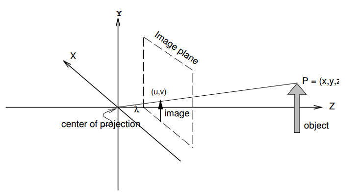 Camera Coordinate System
The camera plane carrying the 2D sensing array is called the image plane and is situated at a distance λ ahead of the center of projection. The optical axis is the central axis along the Z direction that contains the center of projection and the principal point (point of intersection of the optical axis and the image plane).
The concept of perspective projection defines the relationship between the actual object coordinates and its representation in the image plane. Using the pinhole camera approximation, the lens is assumed to be an ideal pinhole located at the focal point of the lens. It casts the light falling onto it, onto the image plane. The world coordinates of a point P(x, y, z), its image plane equivalent and the camera origin are believed to be collinear and give the following relationship between the coordinates.
Reference coordinate frames are important to visual servoing which includes a world frame, a robot base frame, an end-effector frame and a camera frame. Accurate transformations between these frames determine correct target pose for the robot.
IMAGE FEATURES OF INTEREST
There are several micro and macro features in images that become regions of interest for the algorithms. Usually, any region of an image that may have a mathematical representation of pixel manipulation can be a feature. Features could be either hand-crafted and visibly understandable or merely a mathematical representation generated by the computer vision algorithms based on annotated information from training data.
Hand-crafted featurs are very evident and intuitively understandable like edges, blobs and corners among others while other non-standard features are usually learned by CNNs or other ML techniques over the training period.
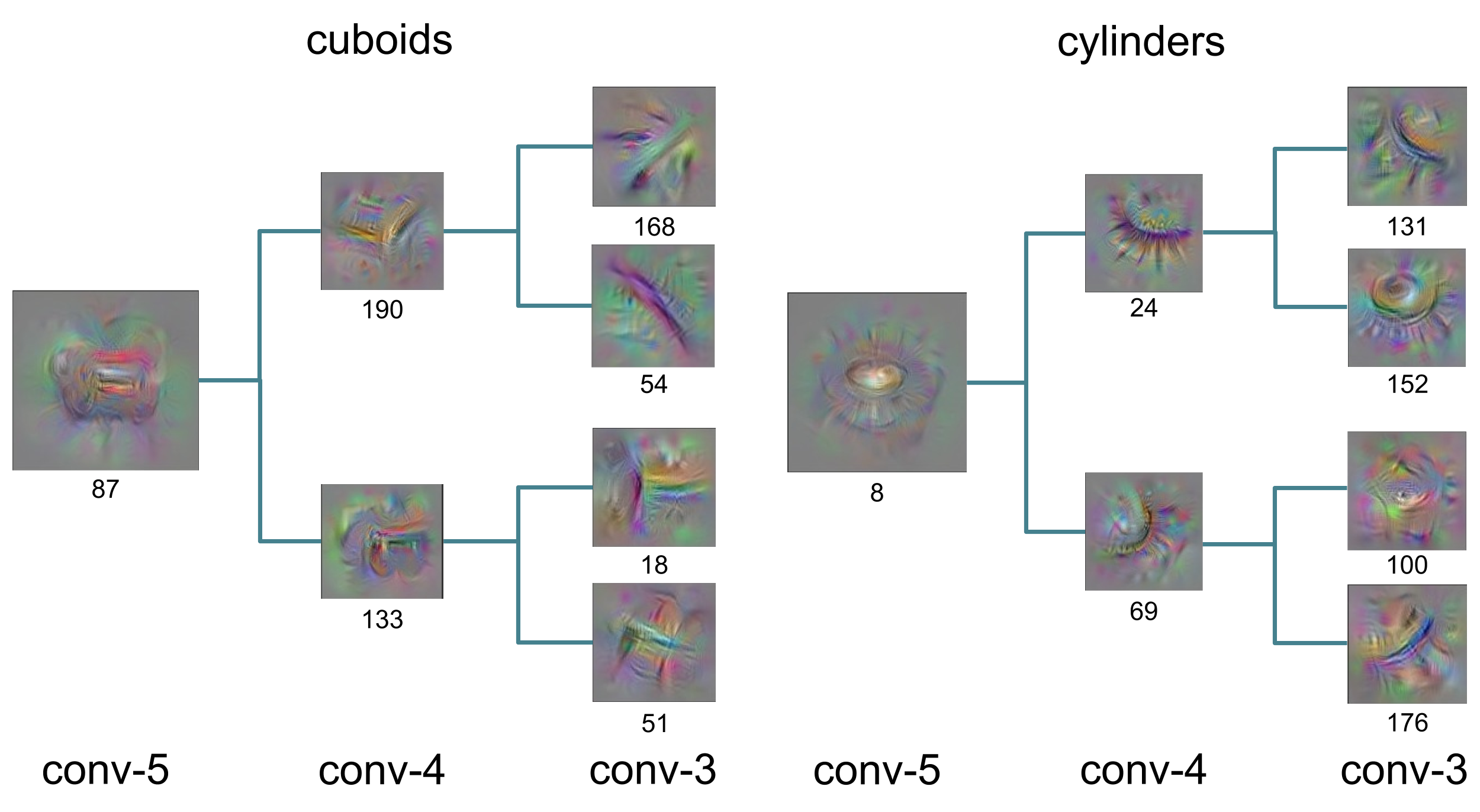 CNN generated features
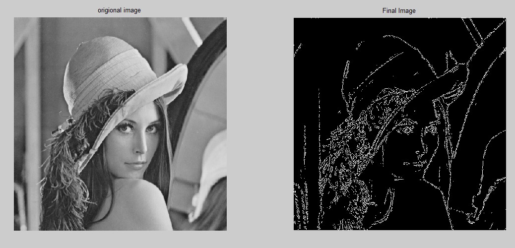 Edges In An Image
This part I of the article is an intuitive walk-through of the high-level concepts of visual servoing. Part II of this topic explains interaction matrices, image jacobians and robot kinematics. It also explains a demo implementation of visual servoing.
 Real Time Operating Systems In Robotics